Drywall studs and tracks may look simple, but consistent production depends on a controlled chain of decisions. Coil condition, material thickness, section geometry, tooling, line setup, cutting, and inspection all influence whether a finished profile matches its drawing. This guide follows the manufacturing route from steel coil to packed products and explains the checkpoints that matter when planning a drywall profile line. Any final machine configuration, material range, and acceptance criteria should be confirmed by the buyer’s drawings, material samples, and technical agreement.
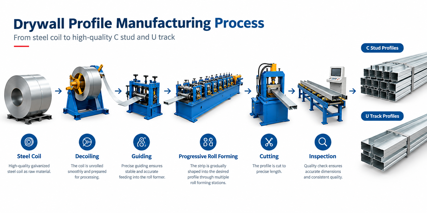
Production planning should begin with the finished profile rather than with a machine model. The drawing defines the section shape, flange and web dimensions, return lips, holes or embossing if required, cut length, and tolerances. The material specification should separately state the steel grade, base metal thickness, coating system, and coil requirements. These details determine the tooling concept and the line processes that may be needed.
A stud and a track belong to the same wall system, but they do not necessarily use identical rolls. A stud commonly has inward returns that help stiffen its flanges, while a track normally provides an open channel that receives the stud. For a broader explanation of profile families, see the keel roll forming machine overview and the guide to U-channel roll forming.
Before equipment selection, send dimensioned drawings for every required section. Do not rely only on a sample name such as “standard stud.” Regional practices and project specifications can differ. Samples are useful for comparison, but an approved drawing remains the clearer basis for technical review.
The manufacturing process usually begins at the decoiler. The coil is loaded, centered, and paid off toward the forming machine. Depending on the agreed line arrangement, the strip may pass through guiding and leveling devices before it reaches the first roll stand. Correct centering is important because a strip that enters at an angle can contribute to asymmetric forming, edge damage, or unstable tracking.
Operators should confirm coil identity against the work order and inspect visible coil condition before running. Material thickness and strip width must correspond to the approved setup. Burr direction, edge quality, telescoping, and surface damage should also be checked according to the factory’s incoming inspection plan. The machine cannot correct unsuitable raw material.
Safe coil handling requires site-specific procedures, suitable lifting equipment, guarding, and trained personnel. These requirements should be included in the factory’s operating and risk-control documents rather than assumed from a generic line description.
Inside the roll former, paired rolls bend the flat strip in a sequence of small steps. The profile should not be forced into its final shape in one station. Progressive forming distributes deformation along the line and helps control twist, bow, flare, and surface marking. The number and design of forming stations depend on the actual section, material, thickness, and quality target; they should be confirmed through technical evaluation rather than selected from a universal formula.
Roll tooling, shaft alignment, stand position, and guide settings all affect the result. During setup, operators normally verify strip entry, observe how each bend develops, and measure the first finished pieces. If a defect appears, the cause may involve raw material, tooling condition, alignment, setup, or the drawing itself. Changing multiple settings at once can make troubleshooting harder.
Readers comparing different section geometries can also review the profile roll forming machine introduction. For available equipment categories, the drywall profile machine range provides a starting point, while project-specific suitability still requires drawing review.
Studs and tracks serve different functions, so their profiles and tooling should be evaluated separately. A buyer may require one dedicated line for each product, or may discuss a changeover concept where technically practical. The right choice depends on the product range, planned batch sizes, changeover expectations, available floor space, labor plan, and production schedule.
| Evaluation item | Stud profile | Track profile | What to confirm |
|---|---|---|---|
| Section form | Often includes return lips | Usually an open channel | Approved cross-section drawing |
| Roll tooling | Designed for the required stud geometry | Designed for the required track geometry | Whether tooling is dedicated or changeable |
| Material | Project-specified steel and coating | Project-specified steel and coating | Grade, base metal thickness, coating, strip width |
| Length control | Set by order or project | Set by order or project | Length range and agreed tolerance |
| Optional features | May include holes or embossing | May include holes or other details | Drawing, location, and process sequence |
A buyer focused on stud production may start with the metal stud machine category. However, the tooling scope and changeover method should be written into the technical agreement. Similar-looking tooling should never be assumed to cover every size.
After forming, profiles are cut to the ordered length. The cutting method and its location in the process depend on the selected line concept and product requirements. The control system coordinates feeding and cutting, but actual length performance must be checked on finished pieces under agreed operating conditions. Where punching, embossing, coding, or other operations are required, their sequence and positional requirements should also be documented.
First-piece inspection should compare the output with the approved drawing. Typical checks include cross-section dimensions, overall length, straightness, twist, burrs, cut-end condition, surface appearance, and any specified hole position. The exact gauges, sampling frequency, and acceptance limits belong in the quality plan. When material or size changes, a new setup approval may be necessary.
Finished profiles should be identified so that product, material batch, size, and production record can be traced according to the manufacturer’s system. Packing should protect edges and coated surfaces during internal movement and shipment. Bundle size, labels, separators, and packaging materials should be agreed according to handling and transport needs.
Can one machine make every stud and track size?
No universal answer applies. Capability depends on the section drawings, size range, tooling design, adjustment method, material, and agreed changeover plan. Submit the complete product list for evaluation.
Which material information is required for a quotation?
Provide the steel grade, base metal thickness, coating specification, strip or coil information, and the applicable product drawings. If a requirement is still undecided, mark it clearly rather than substituting an assumption.
Why is the finished drawing more important than a product name?
Names such as stud, track, keel, or channel can cover different geometries. The drawing establishes the bends, dimensions, features, and tolerances used to assess tooling and line processes.
How should a new line be accepted?
Acceptance should follow the criteria in the signed technical agreement. The parties should define material, test profiles, measurement methods, operating conditions, and required records before the test.
What should a buyer send first?
Send profile drawings, material specifications, required lengths, expected product mix, and any punching or packaging requirements. You can learn more about the manufacturer on the About Us page before opening a technical discussion.
Project next step: Prepare your drawings and material requirements, then request a line review based on documented products rather than generic assumptions.
WhatsApp Code

